
Purple Martin Pages
![]() Requirements for martins
Requirements for martins
![]() The Martin Bio
Page
The Martin Bio
Page![]() The Habits
Page
The Habits
Page![]() Tips to
Attract Them
Tips to
Attract Them
![]() Nest
Checks
Nest
Checks
![]() T-14
Mounting
T-14
Mounting![]() Purple Martin
Housing
Purple Martin
Housing
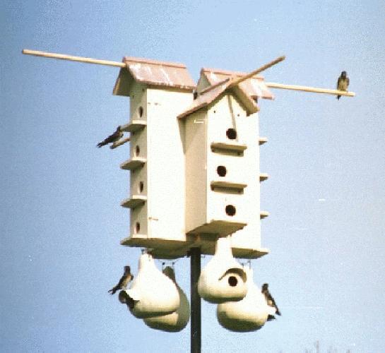
Mounting a T-14ToA Round Metal Pole
Safety Note:
DO NOT USE ROPE FOR THIS DESIGN.
Rope is not
strong enough to handle these loads.
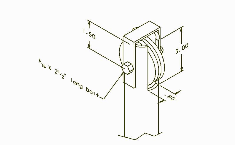
T-14 and Pipe Mounted Pulley SystemThe
following is the detail view of the pulley and safety strap at the
top of my pole that holds my T-14 martin house up. As can be seen,
the pulley is imbedded in the end of the pipe and held in place by a
5/16" x 2 3/4" long bolt. The pulley is centered in the slot with
washers piled onto the bolt on each side of it to keep it
centered. Any commercial machine shop can manufacture these
pulleys. Simply print out this drawing and bring it to
them.
Material: Aluminum
Safety strap: .090 thk Aluminum Inside width equals outside dia of pipe being used. Mounting hole = clearance for bolt being used. Mtg hole, down 2" from inside of bend. Width = 1"
The safety strap over the pulley is required to prevent the cable from accidentally coming out of the pulley groove and can be made from either steel or aluminum, however if made from aluminum, rust is not an issue and it's much easier to work with. The slot can be cut in the end of the pipe using a hand held hacksaw. Take your time and make it as close to the dimensions as possible. Then, drill the hole and add your pulley and safety strap. Assuming you have already mounted your winch, feed the cable through the pulley insuring you are inside the safety strap. Then, string it down to the area where you will be adding your frame. Add a goof thick washer first, then double the cable back on itself and add a small cable clamp to the end of the cable. This forms a knot at the end of the cable which does not allow it to pull through the frame cable hole. The washer simply gives it a smoother and flatter surface to ride on the frames wooden surface.
The Mounting FrameHorizontal MembersThis frame can be made from one 8 foot long piece of treated 2 x 4 lumber. Make sure you get one that is as straight and free of knots as possible. This makes for a better job to start with.
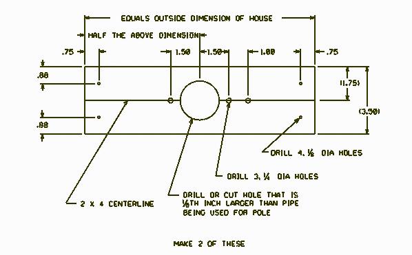
The following graphic shows the dimensions for the two blocks required to mount the T-14 style house to a pipe. These blocks are nothing more than 2 x 4's, and are used to make a frame that the house sections are mounted to. The T-14 is made in 4 sections, each mounting separately to the frame. To make the frame, measure the width of the back of your T-14. That is the dimension for the length of your two horizontal members. Now, cut and make 2 of the following parts. A hand held drill and jig saw are the only two tools required to make these parts. While cutting, cut 2 - 18" long pieces of 2 x 4. These are the vertical members that will be used to make the final frame later.
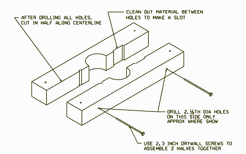
Once all the holes are drilled in the two , use your jigsaw and cut them in half along the centerline indicated. It is best to mark the parts so they can be kept together. The cuts from a jigsaw may not be perfect, but if kept together, the two parts will mate correctly.
Now using your jigsaw, clean out the material between the two 1/4 inch holes. This makes a slot when the parts are re-assembled which allows the cable freedom for movement when raising and lowering the house with the winch.
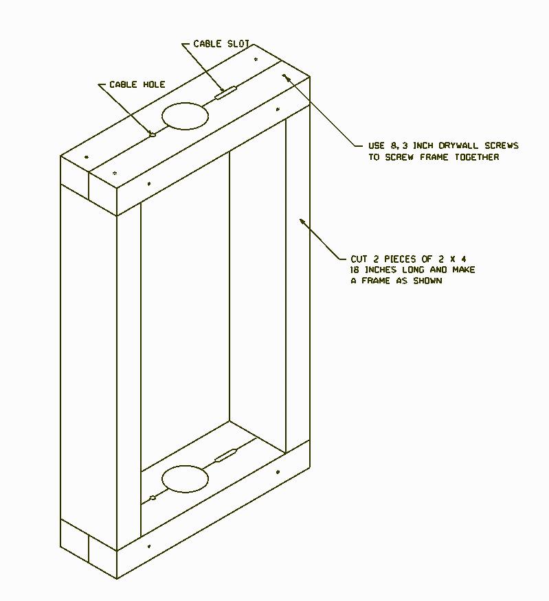
When done, assembly can now begin. Using only the two rear portions of the horizontal members, screw them on to the ends of the vertical members as shown in the 'Final Frame' drawing below. This will give you a basic frame that doesn't have any front halves to the horizontal members.
Now, take the frame to the pipe where it is to be mounted. Might need two people to hold all the parts in place until assembly is final. The following is said assuming the cable has been threaded through the pulley at the top of the pole and is dead ended on the downward end. (Dead ended refers to adding a clamp to the free end of the cable forming a knot large enough so that it won't pull through the cable hole). While the frame is held to the back of the pole, place the up side of the cable, (from the winch) in the half cable slot of BOTH horizontal members. Repeat this procedure for the knot end of the cable placing it in the half holes with the knot on the underside of the lower horizontal member. Now place the front half of the lower horizontal member in position and insuring the cables are in proper position, screw it in place. Repeat for the top front half horizontal member. This now gives you a frame mounted on your pole as shown below.
Final Frame
This frame will be greatly increased structurally with the addition of the 4 housing sections, but first I strongly suggest using some wood preservative and then painting the frame before mounting the house.
Now, on the back of each house section, measure up 21 " from the bottom and draw a horizontal line. Now screw a small block of wood about a 1/2" thick and 2" long to the back of each unit with the bottom of the block resting on the line. I used these blocks of wood to rest my house sections on the TOP horizontal frame member so that it would be easier for me to work with. The 21" allows for the bottom of the house to be flush with the bottom of the frame. You may want to make adjustments to this dimension depending on how you want to mount your house. I mounted my long sections of the house first.
Now, mark and drill 4, 1/8" holes into the back of each long house unit about the middle of the horizontal member, 2 holes for each member. Then, using 4, 1 - 5/8" long galvanized decking screws, screw each long unit in place. Now, the shorter sections of the house can be added in the same fashion screwing into the vertical members of the frame. When all done, you should have a T-14 mounted to a round metal pole as shown below.
Now, you can make a winch run of your house. As you turn the winch and the house raises, notice the cable in the bottom cable slot. It moves with the increase or decrease of the size of the winch pulley. This is why there has to be a slot on the winch side of the frame.
If you look closely under the house in the picture, you can see how I made my lower horizontal members of my frame a little longer. This allows my shorter units of the house to sit on top of the lower horizontal and to be raised the thickness of the 2 x 4. I preferred this look a little better than a perfectly aligned house.
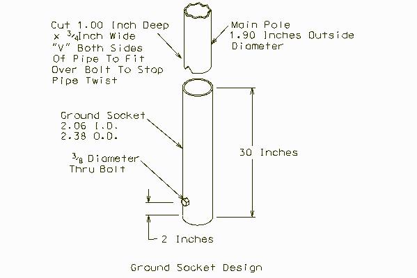
A Ground Socket
Below is a drawing showing how to make a ground socket from Schedule 40 pipe. The main pipe diameter is 1.9 inches Outside Diameter. The socket inside diameter is 2.06 and will allow the main pipe to fit down inside of it very easily. Cut the notch at the bottom of the main pipe to prevent twisting once installed. This ground socket should be buried in concrete with the top of the socket at ground level. Then the main pipe can be removed when ever required. Also, with the top of the socket at ground level, no one will trip over them and also, the mower will slip over the top of them without ruining the mower blades. Then the main pipes can be replaced any time you like.
The main pipes fit fairly loose in the socket, so what I do is push the main pipe to one side and then place 2 - 16 penny spikes beside it down into the ground socket. The heads of the spikes hold the pole to one side so that it doesn't rock in the ground socket and can easily be removed when the main pole needs to be removed.
Note: If you decide on pipe sizes other than given, make sure the two pipes will fit together before you do any work.

|


 1999 -
All Rights Reserved
1999 -
All Rights Reserved